

Introduction issues in mobile communications:-
Mobile Computing is a technology that allows transmission of data, voice and video via a computer or any other wireless enabled device without having to be connected to a fixed physical link. The main concept involves −
Mobile communication
The mobile communication in this case, refers to the infrastructure put in place to ensure that seamless and reliable communication goes on. These would include devices such as protocols, services, bandwidth, and portals necessary to facilitate and support the stated services. The data format is also defined at this stage. This ensures that there is no collision with other existing systems which offer the same service.
 |
| Connective |
Since the media is unguided/unbounded, the overlaying infrastructure is basically radio wave-oriented. That is, the signals are carried over the air to intended devices that are capable of receiving and sending similar kinds of signals.
Mobile Hardware
Mobile hardware includes mobile devices or device components that receive or access the service of mobility. They would range from portable laptops, smartphones, tablet Pc's, Personal Digital Assistants.
 |
| Hadware |
These devices will have a receptor medium that is capable of sensing and receiving signals. These devices are configured to operate in full- duplex, whereby they are capable of sending and receiving signals at the same time. They don't have to wait until one device has finished communicating for the other device to initiate communications.
Above mentioned devices use an existing and established network to operate on. In most cases, it would be a wireless network.
Mobile software
Mobile software is the actual program that runs on the mobile hardware. It deals with the characteristics and requirements of mobile applications. This is the engine of the mobile device. In other terms, it is the operating system of the appliance. It's the essential component that operates the mobile device.
 |
| Mobile Software |
Since portability is the main factor, this type of computing ensures that users are not tied or pinned to a single physical location, but are able to operate from anywhere. It incorporates all aspects of wireless communications.
Cellular Approach
With limited frequency resource, cellular principle can serve thousands of subscribers at an affordable cost. In a cellular network, total area is subdivided into smaller areas called “cells”. Each cell can cover a limited number of mobile subscribers within its boundaries. Each cell can have a base station with a number of RF channels.
Frequencies used in a given cell area will be simultaneously reused at a different cell which is geographically separated. For example, a typical seven-cell pattern can be considered.
Total available frequency resources are divided into seven parts, each part consisting of a number of radio channels and allocated to a cell site. In a group of 7 cells, available frequency spectrum is consumed totally. The same seven sets of frequency can be used after certain distance.
The group of cells where the available frequency spectrum is totally consumed is called a cluster of cells.
Two cells having the same number in the adjacent cluster, use the same set of RF channels and hence are termed as “Co-channel cells”. The distance between the cells using the same frequency should be sufficient to keep the co-channel (co-chl) interference to an acceptable level. Hence, the cellular systems are limited by Co-channel interference.
 |
Cellular Network
|
- Hence a cellular principle enables the following.
- More efficient usage of available limited RF source.
- Manufacturing of every piece of subscriber's terminal within a region with the same set of channels so that any mobile can be used anywhere within the region.
Shape of Cells
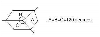
For analytical purposes a “Hexagon” cell is preferred to other shapes on paper due to the following reasons.
- A hexagon layout requires fewer cells to cover a given area. Hence, it envisages fewer base stations and minimum capital investment.
- Other geometrical shapes cannot effectively do this. For example, if circular shaped cells are there, then there will be overlapping of cells.
- Also for a given area, among square, triangle and hexagon, radius of a hexagon will be the maximum which is needed for weaker mobiles.
In reality cells are not hexagonal but irregular in shape, determined by factors like propagation of radio waves over the terrain, obstacles, and other geographical constraints. Complex computer programs are required to divide an area into cells. One such program is “Tornado” from Siemens.
Operating Environment
Due to mobility, the radio signals between a base station and mobile terminals undergo a variety of alterations as they travel from transmitter to receiver, even within the same cell. These changes are due to −
- Physical separation of transmitter and receiver.
- Physical environment of the path i.e. terrain, buildings, and other obstacles.
Slow Fading
- In free space conditions (or) LOS, RF signal propagation constant is considered as two i.e. r = 2. This is applicable for static radio systems.
- In mobile environment, these variations are appreciable and normally ‘r’ is taken as 3 to 4.
Rayleigh Fading
The direct line of sight in mobile environment, between base station and the mobile is not ensured and the signal received at the receiver is the sum of a number of signals reaching through different paths (multipath). Multipath propagation of RF waves is due to the reflection of RF energy from a hill, building, truck, or aero plane etc.; the reflected energy undergoes a phase change also.
If there are 180 out-of phase with direct path signals, they tend to cancel out each other. So the multipath signals tend to reduce the signal strength. Depending upon the location of the transmitter and receiver and various reflecting obstacles along the path length, signal fluctuates. The fluctuations occur fast and it is known as “Rayleigh fading”.
In addition, multipath propagation leads to “pulse widening” and “Inter symbol Interference”.
Doppler Effect
Due to the mobility of the subscriber, a change occurs in the frequency of the received RF signals. Cellular mobile systems use following techniques to counter these problems.
- Channel coding
- Interleaving
- Equalization
- Rake receivers
- Slow frequency hopping
- Antennae diversity
Co-Channel Interference and Cell Separation
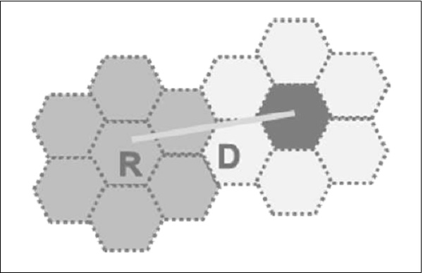
We assume a cellular system having a cell radius “R” and Co-channel distance “D” and the cluster size “N”. Since the cell size is fixed, co-channel interference will be independent of power.
Co-chl interference is a function of “q” = D/R.Q = Co-chl interference reduction factor.Higher value of “q” means less interference.Lower value of “q” means high interference.“q” is also related to cluster size (N) as q = 3Nq = 3N = D/R
For different values of N, q is −
N = 1 3 4 7 9 12
Q = 1.73 3 3.46 4.58 5.20 6.00
Higher values of “q”
- Reduces co-channel interference,
- Leads to higher value of “N” more cells/cluster,
- Less number of channels/cells,
- Less traffic handling capacity.
Lower values of “q”
- Increases co-channel interference,
- Leads to lower value of “n” fewer cells / cluster,
- More number of channels / cells,
- More traffic handling capacity.
Generally, N = 4, 7, 12.
C/I Calculations and ‘q’
The value of “q” also depends on C/I. “C” is the received carrier power from the desired transmitter and “I” is the co-channel interference received from all the interfering cells. For a seven-cell reuse pattern, the number of co-channel interfering cells shall be six in number.
I = m2b∑Mz1 Im
Loss of signal is proportional to (distance) –r
R – Propagation constant.
c α R-r
R = Radius of cell.
I α 6 D-r
D= Co-channel separation distance
C/I = R – r / 6D –r = 1/6 × Dr / Rr = 1/6 (D/R) r
C/I = 1/6 q r since q = D/R and q r = 6 C/I
Q = [6 × C/I]1/r
Based upon the acceptable voice quality, the value of C/I has been found to be equal to 18 dB.
Assuming,
- A seven-cell reuse pattern
- Omni directional antennae
Value of ‘q’ can be typically around 4.6.
Value r is taken as 3.
This is an ideal condition, considering the distance of the mobile units from the interfering cells to be uniformly equal to ‘D’ in all cases. But practically mobile moves and distance ‘D’ reduces to ‘D-R’ when it reaches the boundary of the cell, and C/I drops to 14.47 dB.
Hence ‘freq’ reuse pattern of 7 is not meeting C/I criteria with omni directional antennae.
If N = 9 (or) 12,
N = 9q = 5.2C/I = 19.78 dB
N = 12q = 6.0C/I = 22.54 dB
Hence, either 9 or 12 cell pattern is to be with omni directional antennae, but traffic handling capacity is reduced. Hence they are not preferred.
In order to use N = 7 (or lower), directional antennas are used in every cell site. A cell having 3 sectors is very popular and will be like the figure shown below.
Antenna’s font – back coupling phenomenon reduces number of potential interferers.
For example if N = 7.
With omni directional antennae, number of interfering cells shall be six. With directional antennae & 3 sectors the same is reduced to two. For N = 7 and three sectors, the C/I improves from 14.47 dB to 24.5 dB even in worst conditions. Then C/I meets the requirement of 18dB. For N = 7 and six sectors, the C/I improves to 29 dB.
For Urban applications, N = 4 and a three sector cell is used so that more number of carriers per cell are obtained than N = 7. Also the C/I becomes 20 dB in worst cases.
DAMPS Uses 7/21 cell pattern
GSM Uses 4/21 cell pattern
Advantages of sectoring
- Decrease co-channel interference
- Increase system capacity
Disadvantages of sectoring
- Large number of antennas at the base station.
- Increase in the number of sectors/cell reduces the trunking efficiency
- Sectoring reduces the coverage area, for a particular group of channels.
- Number of ‘Hand offs’ increases.
Hand Off
When the mobile unit travels along a path it crosses different cells. Each time it enters into a different cell associated with f = different frequency, control of the mobile is taken over by the other base station. This is known as ‘Hand off’.
Hand off is decided based on −
- Received signal strength information if it is below a threshold value.
- Carrier to interference ratio is less than 18 dB.
Adjacent Channel Interference
A given cell/sector uses a number of RF channels. Because of imperfect receiver filters, which allow nearby frequencies to leak into pass band, adjacent channel interference takes place.
It can be reduced by keeping the frequency separations between each RF channel in a given cell as large as possible. When the reuse factor is small, this separation may not be sufficient.
A channel separation, by selecting RF frequencies, which are more than 6 channels apart, is sufficient to keep adjacent channel interferences within limits.
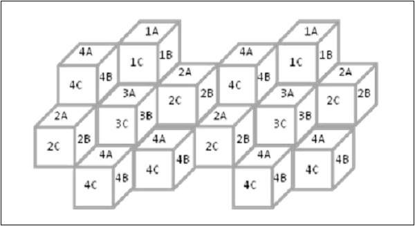
For example, in GSM which follows 4/12 pattern, N = 4
Sectors = 3/cell
 |
| Channel Interface diagram |
IA will use RF Carr. 1, 13, 25,………..
IB will use RF Carr 5, 17, 29,…………
IC will use RF Carr. 9, 21, 33,……….. and so on.
Trunking
Cellular radios rely on trunking to accommodate a large number of users in a limited radio spectrum. Each user is allocated a channel on need/per call basis and on termination of the cell, the channel is returned to the common pool of RF channels.
Grade of Service (GOS)
Because of trunking, there is a likelihood that a call is blocked if all the RF channels are engaged. This is called ‘Grade of Service’ “GOS”.
Cellular designer estimates the maximum required capacity and allocates the proper number of RF channels, in order to meet the GOS. For these calculations, ‘ERLANG B’ table is used.
Cell Splitting
When the number of users reaches a saturation in a start-up cell (initial design) and no more spare frequency is available, then the start-up cell is split, usually in four smaller cells and traffic increases by four and more number of subscribers can be served.
After ‘n’ splits, the traffic will be −
T2 = T0 × 42
Power will be reduced −
P2 = P0 – n × 12 db
Hence cell splitting improves the capacity and lowers the transmission power.
 |
| Cellular |
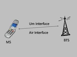
Air Interface in GSM Network:-
GSM stands for global service for messaging. this is the mostly used service for transmission of data and call generation.
in this we use components for connecting the call.
BTS,BSC,MSC,VLR,HLR etc are the main parts of the GSm network.
in this we use components for connecting the call.
BTS,BSC,MSC,VLR,HLR etc are the main parts of the GSm network.
 |
| GSM Interface |


IEEE 802.11
The 802.11 standard is defined through several specifications of WLANs. It defines an over-the-air interface between a wireless client and a base station or between two wireless clients.
There are several specifications in the 802.11 family −
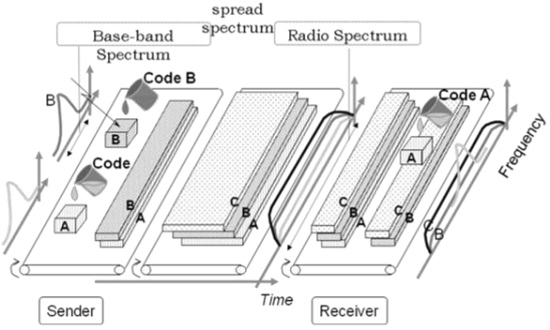
- 802.11 − This pertains to wireless LANs and provides 1 - or 2-Mbps transmission in the 2.4-GHz band using either frequency-hopping spread spectrum (FHSS) or direct-sequence spread spectrum (DSSS).
- 802.11a − This is an extension to 802.11 that pertains to wireless LANs and goes as fast as 54 Mbps in the 5-GHz band. 802.11a employs the orthogonal frequency division multiplexing (OFDM) encoding scheme as opposed to either FHSS or DSSS.
- 802.11b − The 802.11 high rate WiFi is an extension to 802.11 that pertains to wireless LANs and yields a connection as fast as 11 Mbps transmission (with a fallback to 5.5, 2, and 1 Mbps depending on strength of signal) in the 2.4-GHz band. The 802.11b specification uses only DSSS. Note that 802.11b was actually an amendment to the original 802.11 standard added in 1999 to permit wireless functionality to be analogous to hard-wired Ethernet connections.
- 802.11g − This pertains to wireless LANs and provides 20+ Mbps in the 2.4-GHz band.
Here is the technical comparison between the three major WiFi standards.
| Feature | WiFi (802.11b) | WiFi (802.11a/g) |
|---|---|---|
| PrimaryApplication | Wireless LAN | Wireless LAN |
| Frequency Band | 2.4 GHz ISM |
2.4 GHz ISM (g)
5 GHz U-NII (a)
|
| Channel Bandwidth | 25 MHz | 20 MHz |
| Half/Full Duplex | Half | Half |
| Radio Technology |
Direct Sequence
Spread Spectrum
|
OFDM
(64-channels)
|
| Bandwidth | <=0.44 bps/Hz | ≤=2.7 bps/Hz |
| Efficiency | Avg | High |
| Modulation | QPSK | BPSK, QPSK, 16-, 64-QAM |
| FEC | None | Convolutional Code |
| Encryption | Optional- RC4m (AES in 802.11i) | Optional- RC4(AES in 802.11i) |
| Mobility | In development | In development |
| Mesh | Vendor Proprietary | Vendor Proprietary |
| Access Protocol | CSMA/CA | CSMA/CA |


1 Comments
This blog is really helpful regarding all educational knowledge I earned. It covered a great area of subject which can assist a lot of needy people. Everything mentioned here is clear and very useful.
ReplyDeletebts location finder is a tool that provides call detail record relay key metadata for when and how your business phone system is being used. Avenging Security PVT LTD. Introducing a toolkit for taking 2G, 3G, and 4G tower data, which collects cell ID-data from nearby towers, making it easy to use with any Windows system, Free software update for one year.